+86-512-52396378
sales@szuniking.com
sales@szuniking.com
1 Longteng Rd, Tonggang Industrial Park, Changshu ETDZ, Jiangsu Province, China 215511
Views: 0 Author: Site Editor Publish Time: 2026-09-06 Origin: Site


Engineers and procurement teams constantly face a critical design challenge. You must specify the exact thickness and size for PBT material to balance structural integrity, electrical insulation, and production feasibility. Nailing these dimensions determines whether your part succeeds or fails in the field. Proper sizing prevents severe injection molding warpage. It guarantees robust dielectric performance and keeps cycle times highly efficient. Without strict dimensional control, your components risk catastrophic electrical shorts or mechanical fracturing. Modern electronic assemblies demand extreme precision from plastic housings. This article provides a clear, practical framework for evaluating dimensions. We will explore specific sizing requirements based on production methods. You will learn how component applications dictate size limits. Finally, we share necessary risk mitigation strategies for scaling production safely. Read on to master thickness parameters and optimize your next component design for seamless manufacturing.
Dielectric strength relies heavily on wall thickness. Thick sections of pbt directly increase voltage resistance. This property proves essential for connectors, switches, and automotive relays. Engineers calculate required thickness based on expected voltage loads. A standard baseline assumes 20 to 25 kilovolts per millimeter of thickness. You must scale the wall size proportionately to handle higher electrical currents safely. High-voltage electric vehicle components require exact thickness calculations to prevent arc tracking. If you design walls too thin, electrical breakdown becomes inevitable.
Engineers often rely on Comparative Tracking Index (CTI) tests. These tests evaluate how well the polymer resists electrical tracking across its surface. You will find thicker barriers delay electrical tracking significantly. Automotive battery housings rely heavily on these precise thickness calculations. A fraction of a millimeter can mean the difference between passing and failing stringent safety standards.
Designers constantly balance mechanical strength against flexibility. Thicker walls deliver rigid structural integrity. They support heavy loads and resist bending under pressure. Thinner walls allow for snap-fit flexibility. Snap-fit joints need elastic deformation to function properly during assembly. You must pinpoint the exact size limit where rigidity stops and flexibility begins. If you push a snap-fit arm too thick, the joint will snap during installation.
Thermal management also depends entirely on part dimensions. Wall thickness changes how quickly heat dissipates into the surrounding air. Continuous-use environments demand careful thermal planning. Under-hood automotive parts experience intense, repeated heat cycling. Bulky sections trap heat internally. This trapped heat accelerates material degradation over time. Thinner, uniform walls promote faster, more consistent cooling. They help electronic housings shed internal operating heat efficiently.
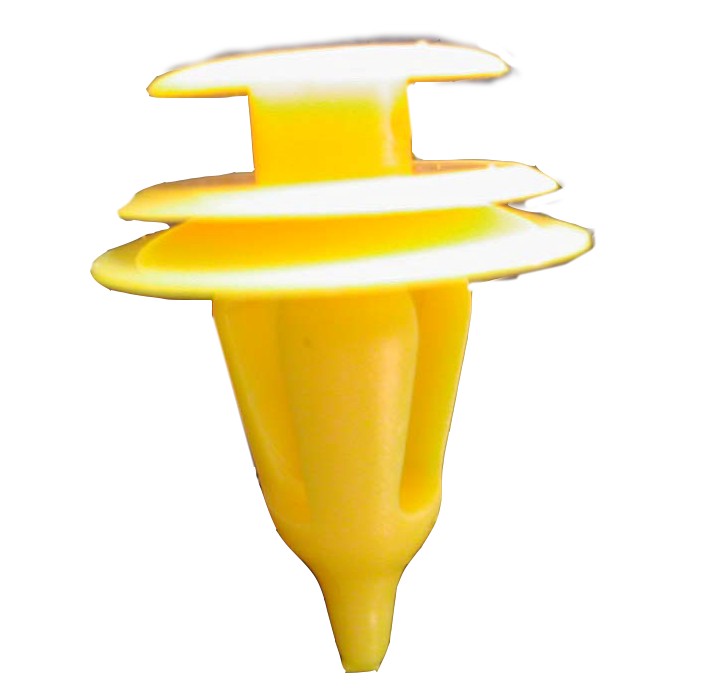
Injection molding dictates specific sizing rules for optimal results. Standard acceptable ranges fall between 1.0 mm and 3.0 mm. You must maintain uniform wall thickness across the entire part. Uniformity prevents unsightly sink marks on cosmetic surfaces. It also stops internal voids from forming inside the plastic. Drastic changes in thickness disrupt the polymer flow front during injection.
To achieve optimal results, adhere to these fundamental molding guidelines:
Glass-filled grades demand slightly different engineering rules. A 30% glass-filled mixture requires thicker minimum walls. These larger dimensions accommodate glass fiber flow during high-pressure injection. Thicker walls also reduce internal stress caused by fiber orientation. If you force glass-filled resin through a 0.5 mm gap, the fibers jam. This jamming causes premature gate freeze and short shots.
CNC machining relies on entirely different sizing constraints. Prototyping and low-volume production use extruded rod, sheet, and plate stock. Machinists typically buy sheets ranging from 10 mm to 50 mm thick. Rod diameters often span 15 mm to 100 mm. These massive blocks allow for extensive material removal during the subtractive process.
You must carefully review raw PBT material specifications before machining. Thick extruded stock sometimes contains internal voids. These microscopic gaps occur during the extrusion cooling process. The outside cools faster than the core, tearing the inside apart. They weaken the final machined component. Always ask your supplier for void-free certifications on thick stock blocks.
Table 1: Standard PBT Thickness Guidelines by Method
| Manufacturing Method | Recommended Thickness | Primary Constraint |
|---|---|---|
| Unfilled Injection Molding | 1.0 mm - 2.5 mm | Flow length and visual sink marks |
| Glass-Filled Injection Molding | 1.5 mm - 3.0 mm | Fiber flow and internal molded stress |
| CNC Machined Sheet Stock | 10.0 mm - 50.0 mm | Internal void formation during cooling |
Even highly optimized polymers have strict physical limits. This resin excels in dimensional stability and electrical insulation. However, thick-walled parts often become brittle under high-impact stress. Sudden mechanical shocks easily fracture rigid, bulky cross-sections. You must acknowledge these impact limitations during the early design phase. Ignoring them leads to catastrophic field failures.
Sometimes, applications demand a different polymer altogether. You need a clear decision matrix for transitioning to a pom material with high toughness. Consider this switch for specific challenging scenarios:
Engineers often build a decision matrix to evaluate these parameters. You map out impact strength, friction coefficients, and continuous operating temperatures. When impact strength dominates the requirements, the acetal option wins. When electrical insulation dominates, you stick with the original polyester base. This objective comparison removes guesswork from your engineering process.
You must weigh the cost-to-performance ratio carefully. Standardizing on acetal alternatives changes scalability costs significantly. Compare material prices across varying part thicknesses. Evaluate manufacturing expenses by looking at direct piece-part costs. Tougher acetals might increase upfront raw material spend. However, they drastically reduce scrap rates for impact-prone geometries on the factory floor.
Uneven thickness leads directly to differential cooling rates. Thick sections cool much slower than thin sections. This mismatch creates severe internal stress within the molded part. The stress releases as part warpage after mold ejection. Warpage remains a primary reason plastic parts fail quality assurance testing. Flat surfaces bow, and critical mounting holes shift out of alignment.
Engineers deploy several mitigation strategies to fight warpage. Coring removes unnecessary material from bulky features. It effectively hollows out thick sections while maintaining structural ribs. You should also implement gradual transitions between varying sizes. Use generous chamfers and radii instead of sharp 90-degree corners. Gradual transitions smooth out the cooling gradient naturally.
Tool makers combat these risks by designing conformal cooling lines. Conformal cooling wraps water channels around the thickest features of the mold. It pulls heat away from bulky sections faster. You must collaborate with your tool builder early in the process. Discussing wall thickness during the CAD phase saves thousands of dollars in mold rework.
Mold operators also adjust temperatures and gating strategies based on the specific thickness profile. Strategic gate placement pushes molten plastic into the thickest regions first. This approach packs the mold efficiently and reduces localized shrinkage.
We must address a transparent assumption regarding fiber reinforcement. Glass-filled variations shrink anisotropically. They shrink differently in the flow direction compared to the transverse direction. Fibers align parallel to the injection flow. This alignment resists shrinkage along the flow path. However, the plastic still shrinks heavily across the flow path. This anisotropic behavior makes thickness uniformity fundamentally critical for flat parts.
Partnering with the right vendor ensures long-term production stability. You must vet a PBT material supplier based on their tolerance capabilities. Ask for statistical process control data during your audit. They must deliver consistent dimensional tolerances across high-volume runs. Inconsistent resin batches cause unpredictable shrinkage during molding. Unpredictable shrinkage destroys your carefully calculated tooling dimensions.
Evaluate their material grade expertise thoroughly. Ask suppliers about their specific portfolio options. Request details on unfilled, glass-reinforced, and flame-retardant UL94-V0 grades. Different grades dictate allowable part sizes and minimum wall thicknesses. A knowledgeable vendor will steer you toward the correct grade for your geometry. They warn you before you specify an impossible combination.
Compliance and documentation remain non-negotiable for engineering plastics. Ensure your vendor provides comprehensive Material Data Sheets (MDS). These documents must detail melt flow characteristics and precise shrinkage rates. They should also include dielectric testing data relevant to your specific thickness requirements. Thorough documentation proves the resin meets stringent industry standards. It protects your company from liability during product safety certifications.
Moisture control represents another critical evaluation metric. This polymer absorbs moisture from the atmosphere easily. Moisture degrades the polymer chains during the melting process. Your vendor must ship the resin in moisture-proof, sealed packaging. Ask them about their lot-to-lot moisture testing protocols. Superior vendors provide drying guidelines alongside their technical data to ensure flawless production.
Specifying the right size involves strict balancing acts. You must intersect electrical needs, mechanical loads, and overall moldability. Adhering to proper sizing rules prevents costly manufacturing defects. It guarantees your components pass rigorous safety certifications and perform flawlessly in harsh environments.
Take action by applying these principles to your engineering workflow today:
Proactive design adjustments secure better production outcomes. Master your material dimensions to build superior, long-lasting products.
A: The typical minimum wall thickness sits around 1.5mm. This dimension ensures proper glass fiber distribution during injection molding. Thinner walls restrict movement and cause the flow to freeze prematurely. Maintaining this minimum prevents weak spots and reduces internal molding stress.
A: Yes, material thickness directly impacts flame retardancy ratings. Safety standards like UL94 V-0 tie compliance to specific dimensions. Thicker walls generally achieve these safety ratings much easier than thin-walled sections. The added bulk resists ignition and slows down flame spread effectively.
A: Shrinkage depends heavily on the specific material grade and part bulk. Unfilled grades typically shrink between 1.5% and 2.0%. Glass-filled grades shrink significantly less, ranging from 0.4% to 0.8%. Bulkier, thicker parts trap heat longer, which can slightly increase these shrinkage rates during cooling.